


Abstract
Aortic root (AoR) components provide synchronous and precise 3D deformation of the aortic root during the cardiac cycle in order to ensure closure and opening of the three leaflets over a lifetime. Any deviation from the natural 3D morphology, such as with AoR annulus dilatation, enlarged sinuses and/or dilatation of the sinotubular junction, as in the case of ascending aortic dilatation, may result in disruption of the natural AoR function. Surgical treatment of AoR pathology has two modalities: the replacement of the aortic valve by artificial prosthesis or by preservation of the three leaflets and reconstruction of the aortic root components. Currently, there are two basic aortic root reconstruction procedures: aortic root sparing and aortic valve reimplantation techniques. Regardless of the technique used, the restoration of adequate cusp coaptation, is from a technical point of view, the most important element to consider. To achieve this, there are two requirements that need to be met: (i) the valve coaptation should be superior to the level of the aortic root base by at least 8 mm and (ii) the coaptation height per se has to be ≥5 mm. Successful restoration of the aortic root requires adequate technical skills, detailed knowledge of aortic root anatomy and topography, and also knowledge of the spatial pattern of AoR elements. Recently, there has been growing interest in aortic root reconstructive procedures as well their modifications. As such, the aim of this review is to analyse aortic root topography and 3D anatomy from a surgical point of view. The review also focuses on potential risk regions that one should be aware of before the surgical journey into the ‘deep waters area’ of the AoR begins.
INTRODUCTION
The aortic root is a 3D structure, positioned at the transition of the left ventricular outflow tract and the ascending aorta. Its central components are the three sinuses that represent the bulging part of the aortic root (AoR), the three leaflets and intervalvular triangles (IVTs). The superior border is easy to identify; the sinotubular junction (SJ) is a circular structure representing a transition between the bulging part of the AoR and the tubular ascending aorta (Fig. 1). The three commissures at the SJ level represent an outpost of the leaflet attachments and may be considered as the upper border of the semilunar valve attachment [1, 2] (Fig. 1). The impact of the conjoined morphology of the SJ and commissures on proper valve closure may be well observed in isolated ascending aortic dilatation. The conjoined dilatation of the SJ augments the intercomissural distance and results in an incompetent aortic valve coaptation [3–5]. The same phenomenon may be observed in acute type A aortic dissection, where the acute dilatation of the ascending aorta and of the SJ results in valve insufficiency.
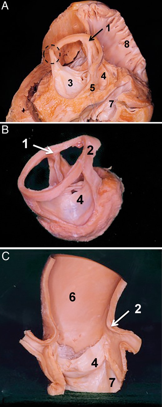
Sinotubular junction as the superior border of the aortic root. (A) Dry dissected aortic root in situ. The aortic root is seen from the superior right view. The right ventricle, right atrium as well the left atrium were removed. The wall of the three sinuses of Valsalva was also removed. The sinotubular junction is in situ over the non-coronary and the right coronary sinus; over the left coronary sinus it was removed. In this view, one can clearly see that the three commissures are at the level of the sinotubular junction. (B) Isolated aortic root where the three sinuses of Valsalva were removed. The sinotubular junction is in situ. One can again observe that the three commissures are at the same level as the sinotubular junction. (C) The vertical section of the ascending aorta and the aortic root. The section plane is positioned at the middle of the left and right coronary artery ostium. Leaflets of the right and left coronary sinus were removed. Specimens show that the sinotubular junction represents a transition between the sinuses of Valsalva and the tubular part of the ascending aorta. 1. Commissure over the right intervalvular triangle, 2. Sinotubular junction, 3. Left aortic valve leaflet, 4. Right aortic valve leaflet, 5. Posterior intervalvular triangle, 6. Ascending aorta, 7. Membranous septum and 8. Right atrium.
AoR base anatomy is much more complex when compared with that of the SJ. It is a virtual line that may not be identified at the first gaze. The AoR base is defined by the base of the IVT and deepest points of the valve attachments. As such, it includes elements of the membranous septum, mitral valve (MV) and left ventricular muscle [2, 6, 7] (Fig. 2). It is elementary for the outcome of the AoR reconstructive procedures to be aware of AoR base morphological complexity [8].
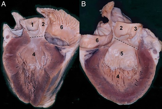
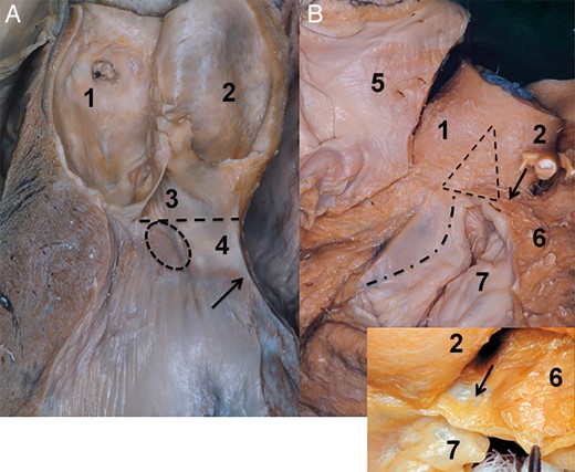
Aortic root base, inferior border to the aortic root. The section plane on the presented specimen runs through the left side of the non-coronary sinus. (A) In this specimen, the aortic root base is seen at the nadirs of the right and the non-coronary sinus. Note at this level that the aortic root base runs over the transition between the right intervalvular triangle and the membranous septum. The dashed line indicates the aortic root base at this level. Note that the transition between the membranous septum and the intervalvular triangle is continuous. (B) Right side of the specimen. The dashed line of the aortic root base over the mitral valve is presented. The leaflets of the non- and the left coronary sinus are left in place. Here, also the transition between the posterior intervalvular triangle and anterior mitral valve leaflet is seen. 1. Right coronary sinus, 2. Non-coronary sinus, 3. Left coronary sinus, 4. Left ventricle, 5. Anterior leaflet of the mitral valve and 6. Left atrium.
It is more than clear that the AoR with its very complex structure is responsible for sequences of well-defined morphological changes during the cardiac cycle. Unfortunately, with the exception of some authors, in an everyday surgical practice, the AoR is interpreted as a symmetrical structure. Some unclarity about the structure of the AoR still exists, despite complex interventions, such as AoR repair and valve reimplantation, that are performed on a regular basis. In my opinion, there is still a major lack of surgical as well as functional oriented 3D interpretation of AoR morphology. The lack of such a descriptive morphology clearly contributes to the mystification and difficulty in the reproducibility of AoR reconstructive procedures.
This review looks at and discusses the detailed morphology of AoR anatomy with a focus on reconstructive procedures. The topography of the AoR is pointed out along with insights into supra-microscopical morphology analysis of the AoR base.
LEAFLETS OF THE AORTIC ROOT
Natural AoR asymmetry emerges from differences in the shapes of AoR components and, as a result, the planes of the SJ and AoR base are not parallel and enclose at a tilted angle. This tilt of the SJ plane over the AoR base means that the three commissures of the leaflets are not at the same level [2, 8]. The asymmetric pattern in a healthy AoR is as follows: the right coronary sinus (RCS) is larger than the left (LCS) and the non-coronary sinus (NCS). This sinus arrangement is followed by different sizes of the IVTs. Both triangles alongside the RCS have similar height and the left IVT is the smallest [2, 9].
To achieve correct leaflet coaptation during the AoR reconstruction/valve reimplantation, the spatial arrangement of the IVTs and the correct position of the three commissures have to be respected. By this, the right and anterior commissure has to be reimplanted in the same plane, whereas the left commissure should be positioned deeper. Apart from the mentioned position of the three commissures, it is important to consider the nature of valve coaptation [5, 10]. The aortic leaflet may be divided into three subsequent segments: the lunula area not larger than 5 mm that is effectively responsible for the coaptation, body of the leaflet and the nadir, and are functioning as hinge of the valve (Fig. 3). The coaptation of the three leaflets is limited to the lunula region and does not exceed the 5 mm. In the normal situation, the coaptation area is superior to the level of the AoR base.
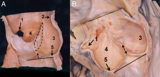
Morphology of the aortic valve coaptation. (A) Isolated aortic root is seen in the vertical plane. Section plane runs through the middle of the non-coronary sinus and the left intervalvular triangle. The coapatation between the right and non-coronary leaflets is seen. The coaptation between two leaflets is marked with a dashed line. Solid line at the aortic root base marks the plane of the aortic root base. The arrow indicates that the coaptation in a normally functioning aortic valve is beyond the aortic root base. (B) Coaptation of the leaflets as seen in the frontal view. The section plane of the aortic root is placed through the middle of the non-coronary sinus and ostium of the right coronary artery. Double arrow indicates the height of the coaptation. This is around 10–5 mm high. The solid line between the nadirs of two sinuses indicates the base of the aortic root. 1. Right coronary artery, 2. Sinotubular junction, 3. Non-coronary sinus, 4. Right coronary sinus and 5. Nadir of the right coronary sinus.
The lunula is quasi-suspended between two commissures; consequently, it becomes clear how important it is to consider the correct position of the commissures in reconstructive procedures. The relation between the leaflet coaptation resp. the lunula and the commissures is as simple as a relation between an anchor and suspension cables in a suspension bridge; the larger the distance between the anchors, the greater are the tension and restriction (Fig. 3). Thus, by understanding these mechanics, it is evident that the distance between commissures is essential for optimal lunula positioning and proper valve function. Thus, the size of the tubular graft is one of the key elements for success.
According to the recent literature dealing with long-term results after valve reimplantation and AoR reconstruction [5, 10–12], the optimal valve sealing function during diastole is reached if the height of the coaptation of three leaflets is around 3–4 mm. Respecting this, excellent long-term results over 10 years may be achieved [11, 12].
To correctly evaluate the size of the tubular graft implanted in a root reconstructive procedure, it is advisable that, after the three sinuses are excised, the three commissures are pulled up in a vertical direction. In doing so, the first instance gives the surgeon an opportunity to judge the relationships between the three commissures and the height of the IVTs. Additionally, with vertical pulling on the commissures, one brings the IVTs into their most anatomical position, and thus, the three leaflets come into a position as seen at diastole, where coaptation is maximum. At this point, a calliper, such as that used for implantation of a stentless bioprosthesis, may be used to determine the ideal size of the SJ, and with this the graft size to be implanted. With a straight graft, the commissures are positioned in a straight vertical line over the AoR base and with this the optimal coaptation is assured. One can also understand why the sinus Valsalva was not eventually accepted in AoR repair procedures. In a Valsalva graft, the IVTs are sewn in a spherical configuration that may result in augmentation of intercommissural distances and consequent leaflet restriction.
INTERVALVULAR TRIANGLES AND AORTIC ROOT BASE
The IVTs may be considered as a skeleton of the AoR, serving as an anchoring pillar for the attachment of the three leaflets. The base of each IVT and the nadir of each sinus create the AoR base. The AoR base is a very complex structure and represents transition between the left ventricular outflow tract and the AoR. Its components are a part of the left ventricle from a physiological aspect as well as a part of the aorta from a morphological aspect. It is a very complex structure, being formed of the MV, of the central fibrous body as well of the left ventricle. The conjoined structure of the IVTs and of the AoR base suggests that discussing the anatomy of the former cannot be done successfully without mentioning the latter and vice versa. Thus, in this section, the anatomy of the AoR base as well as that of the IVTs will be mentioned. As mentioned previously, the three IVTs are not of the same size; the right and the anterior IVTs are larger than the left IVT [2, 9].
The posterior IVT is positioned over the anterior leaflet of the MV. Its base is a virtual line between the nadir of the NCS and the LCS, and corresponds to the superior edge of the MV hinge area. Consequently, the fibrous tissue of the anterior leaflet of the MV continues into the fibrous tissue of the posterior IVT (Fig. 4). By inspection from outside, the inferior border of the posterior IVT may be defined by the attachment of the anterior wall of the left atrium (LA) to the MV leaflet. One can state that the AoR base from inside as well as from outside corresponds to the straight line at the nadirs of the NCS and LCS and the base of the posterior IVT. Thus, the AoR base in the segment between the NCS and LCS is positioned at the central fibrous body. Briefly, the central fibrous body is a fibrous skeleton of the heart between the left and the right fibrous trigone [13] (Fig. 4).
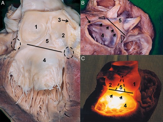
Posterior aortic root base topography. (A) Posterior aortic root base and its relation to the anterior leaflet of the mitral valve are seen in this specimen. The leaflets of the left and the non-coronary sinus were removed. The solid line indicates the posterior base of the aortic root. This is between the nadir of the non- and the left coronary sinus. Of note is that the border between the posterior intervalvular triangle and anterior mitral valve may not be defined by the unaided eye. The dashed circles indicate the right and the left fibrous trigonum. (B) Posterior view of the aortic root base. The three sinuses were removed, as well the left and the right atrium. The attachment of the left atrium was left in situ. The aortic root is seen from the posterior aspect; the solid line marks the aortic root base, and the small arrows indicate the left atrial attachment. It is important to note that the left atrial attachment is positioned inferiorly to the aortic root base. The triangles at the bottom of the non- and the left coronary sinus correspond to the right and the left fibrous trigonum. (C) Topography of the posterior intervalvular triangle as presented with the transillumination technique. In this specimen, the left atrium was removed, and the aortic root is seen from the posterior aspect. A cold light source was positioned into the left ventricle. In this way, the borders of the posterior intervalvular triangle in relation to the left atrial attachment appear much more clear. The arrows indicate the left atrial attachment which is positioned below the base of the intervalvular triangle. 1. Non-coronary sinus, 2. Left coronary sinus, 3. Left coronary artery, 4. Anterior leaflet of the mitral valve and 5. Posterior intervalvular triangle.
In the case of the left and the right IVT, the internal AoR base projection on the superficial surface of the AoR is not that simple as it is in the case of the posterior IVT. The right IVT is positioned between the NCS and the RCS, where its base directly continues into the membranous septum of the interventricular septum. The border of the membranous septum and the IVT is a straight line between the nadir of the NCS and the RCS and, as such, corresponds to the AoR base; it is a fact that the transition between the IVT and membranous septum cannot be identified by the unaided eye. At this point, the left main branch (LMB) of the conduction system enters the left ventricle, just underneath the RCS between the membranous and muscular septum. Its close proximity to the RCS leaflet depends on the size of the membranous septum; with a small membranous septum size, the LMB is close to the RCS leaflet (Fig. 5).
Topography of the right-sided aortic root base. (A) Vertical view of the left ventricular outflow tract and the aortic root. Section plane is through the middle of the non-coronary sinus and the left intervalvular triangle. The arrow indicates the transition between the membranous and the muscular septum. The dashed line indicates the aortic root base; note also the transition between the membranous septum and the intervalvular triangle. The dashed circle shows the position of the left main branch of the heart conduction system. From the topography, it becomes clear: in the large membranous septum the transition area of the LMB is far from the nadir of the right coronary sinus. The opposite is true in the small membranous septum. (B) Relation of the right intervalvular triangle and of the right ventricle. In the large image, the right atrium was removed. The interatrial septum is seen from the right side; it is positioned behind the non-coronary sinus. The aortic root, right intervalvular triangle and the right ventricle are seen from the superior right view. The dashed triangle indicates the right intervalvular triangle. The curved dash-pointed line corresponds to the attachment of the septal leaflet. This is inferior to the right intervalvular triangle base. The arrow indicates the right ventricular muscle being conjoined to the aortic root at the level of the right intervalvular triangle and the right coronary sinus. The inset shows the membranous structure of the right ventricle that is conjoined to the mentioned aortic root area. Note that deeply positioned sutures may easily damage this membranous element. 1. Non-coronary sinus, 2. Right coronary sinus, 3. Right intervalvular triangle, 4. Membranous septum, 5. Right atrium, 6. Right ventricle and 7. Tricuspid valve.
On the outer surface, the AoR base anatomy in the region between the nadir of the NCS and that of the RCS is very complex. At the nadir of the NCS, the conjoined attachment of the right atrium (RA) and the LA is found. The interatrial septum, in the neutrally oriented AoR, indicates the middle of the NCS [13]. The tricuspid valve (TV) with the septal leaflet attachment and anterior commissure is placed just inferior to the right IVT, and normally is never found superior to the right IVT base (Fig. 5).
The right IVT is on the outer surface conjoined to the lateral wall of the RA, and at its base becomes closely related to the right ventricle (RV) (Fig. 5). The relation between the RV and AoR is complex. The RV muscle attachment to the AoR is found lateral and superior to the anterolateral commissure of the TV, at the inferior part of the right IVT and the posterior part of the RCS. In some cases, the RV attachment at the mentioned location may also be present as a membranous structure [13] (Fig. 5). Being aware of this weak area of the RV in the proximity of the right IVT and of the RCS, one can also understand the potential danger during valve reimplantation or AoR annuloplasty; namely, the suture line used at the AoR base may accidentally traverse the weak RV membranous segment. As a result, a damage of the RV with unpleasant haemorrhage may occur as a consequence [14].
One may have the impression that, at the RCS, the RV is attached to the AoR. This special relation was interpreted as a natural diminution of the RCS height and consequently gives the impression of the highly positioned AoR base [15]. Evaluating the relation of the RV, AoR and the LV in a cross section of the left ventricular outflow tract, one can realize that the LV muscular septum serves as the conjoined attachment of the AoR and the RV outflow tract (RVOT; Fig. 6). As presented on specimen (Fig. 6), one can clearly see that the RCS and with this also the AoR are attached to the more internal part of the LV septum, and that the RVOT is conjoined to the more external segment of the septum. From the mentioned topography, it becomes clear that the RCS and the left IVT are not attached to the RVOT (Fig. 6); the details of this topographical relation of the RVOT and RCS may be examined also on a histological specimen (Fig. 6).
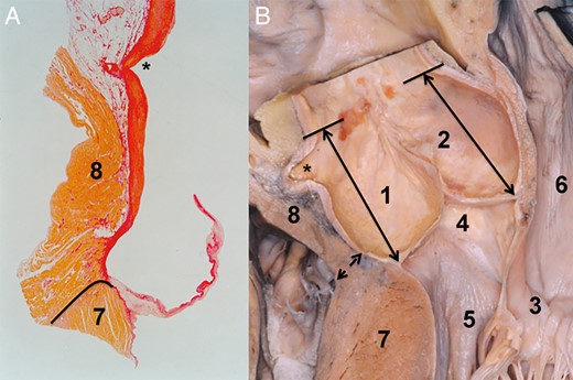
Relationship between the right coronary sinus and the right ventricle. (A) Histological specimen of the right coronary sinus and the right ventricular outflow tract. The staining of the specimen was with haematoxylin–eosin. The connective tissue, the white area between the aortic root and the right ventricular muscle, may be followed just to the level of the valve attachment. The border between the right ventricular muscle and the left ventricle is indicated by a solid line. The asterisk marks the opening of the right coronary artery. (B) Dry dissected specimen showing the relation between the right coronary sinus and the right ventricular outflow tract. The double arrow marks the border between the right ventricle and the left ventricular muscle. The double arrows positioned in the non- and the right coronary sinus serve to demonstrate the distance from the aortic root base to the sinotubular junction. Note that the distance in both sinuses is almost similar. In this specimen, the fact that the right ventricle is not attached to but rather conjoined to the aortic root is well demonstrated. The asterisk marks the opening of the right coronary artery. 1. Right coronary sinus, 2. Non-coronary sinus, 3. Mitral valve, 4. Membranous septum, 5. Left ventricular outflow tract, 6. Left atrium, 7. Left ventricle and 8. Right ventricle.
The left IVT is positioned between the LCS and RCS just behind the RVOT. At this point, it is important to mention that in the case of a highly positioned pulmonary root, the left IVT is behind the posterior wall of the infundibulum, and in the deep pulmonary artery trunk it is conjoined to the pulmonary root. The left IVT is anchored directly to the left ventricular muscle, and consequently, the left IVT that is defined by the virtual line between the nadirs of the left and right sinuses corresponds to the muscle of the lateral wall of the left ventricle. Furthermore, the basal one-third of the left IVT is of muscular structure and the upper two-thirds of the left IVT is of a fibrous structure (Fig. 7). The AoR base belonging to the LCS is in its anterior part anchored to the LV lateral wall, whereas the segment from the left fibrous trigonum of the posterior IVT is conjoined to the P1 segment of the MV.
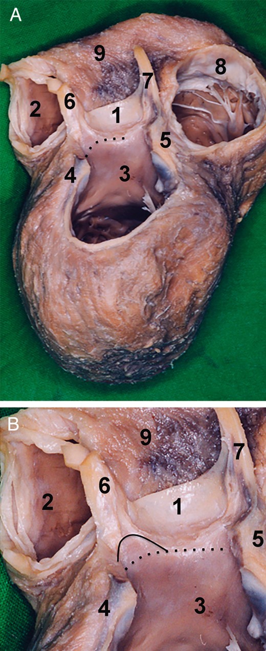
Morphology of the left aortic root base. (A) Dry dissected specimen of the heart after the removal of the mitral valve, left atrium, right atrium and sinuses of Valsalva. The specimen is seen from the superior posterior view. The left aortic root base is positioned between the nadir of the right coronary sinus and the nadir of the left coronary sinus. The aortic root base is at this level is of muscular structure. The muscle corresponds to the left ventricular outflow tract. The aortic root base is indicated by the pointed line. (B) The inferior one-third of the left intervalvular triangle is of left ventricular muscle. The superior two-thirds is of fibrous tissue. The border between the two elements is marked by a solid line. The aortic root base is marked by a pointed line. 1. Right coronary sinus, 2. Right ventricular outflow tract, 3. Left ventricular outflow tract, 4. Left fibrous trigonum, 5. Right fibrous trigonum, 6. Left intervalvular triangle, 7. Right intervalvular triangle, 8. Tricuspid valve and 9. Right ventricle.
TOPOGRAPHY OF SINUSES OF VALSALVA
The NCS is a posterior sinus, being positioned just in front of the anterior wall of the LA and RA. The interatrial septum normally divides the NCS into two separate halves, a left and right half. Dissecting the NCS away from the anterior wall of the LA and RA is a relatively simple act; however, one should keep in mind the thin-walled structure of the RA and that coincidental damage of the RA is very much probable at this level.
The RCS is almost entirely positioned behind the muscle of the right ventricle. The only free segment is at the border to the right IVT. As mentioned before, the RV attachment to the AoR at the level of the RCS to the right IVT transition may be of a membranous structure. This area is also called the right coronary fossa. The right coronary fossa is the space between the RVOT and the RA and contains the initial segment of the right coronary artery.
The lateral part of the LCS is placed in the left coronary fossa, a virtual space between the RVOT and/or pulmonary root and LA, containing the left main coronary artery and the coronary sinus.
AORTIC ROOT REMODELLING AND ROOT IMPLANTATION
An AoR remodelling procedure with restoration of the sinuses is, in some instances, an intuitively more physiological aortic valve-sparing procedure when compared with the reimplantaion technique [16]. This procedure was first described in the last century [17] by Yacoub et al. and is nowadays in general an acceptable method for repair of AoR dilatation in elderly patients with normal AoR base dimension [18, 19]. Root remodelling unfortunately does not address the late AoR base dilatation in young patients with enlarged AoR elements. To prevent later reoperation, the procedure is proposed in elderly patients with dilated sinuses and ascending aorta, but normal dimensions at the AoR base [19].
Following the dissection of the AoR from the surrounding tissue, the excision of three sinuses is performed. Approximately 5 mm of the tissue wall is left just superior to the valve attachment in order to provide graft to the AoR suture. Three commissures are pulled in a straight direction in order to judge optimal SJ diameter and with this the graft size. The graft is tailored according to the size of the sinuses. The height of the sinuses is determined by the height of the leaflet attachments and the IVTs. The RCS and the NCS are approximately equal in size and are larger when compared with the LCS [2, 9]. The width of the intercommissural distances, which determines the width of the tailored neo-sinuses, also follows the aforementioned rule, where the NCS and RCS have a similar intercommissural distance where the width of the LCS is smaller [2, 9].
As mentioned, the AoR reimplantation provides a better physiological AoR function as compared to the reimplantation technique. This is probably due to the preservation of the AoR base physiology; however, the late dilatation of the AoR base and consequent need for reintervention is a major drawback of AoR reconstruction. To prevent this late dilatation, the AoR annulus device was introduced with the idea of prevention late dilatation of the AoR base [14]. However, if this technique in combination with AoR remodelling may provide excellent results of valve reimplantaion is not clear. Furthermore, the long-term results will confirm the efficiency of this new surgical method in prevention of AoR base dilatation.
DAVID PROCEDURE AND AORTIC ROOT ANATOMY AND ANATOMICAL PITFALLS
The steps for aortic reimplantation to the stage of excision of the three sinuses are similar to those in the Yacoub procedure. Prior to positioning of the stitches inferior to the leaflet attachments, the aortic AoR base has to be dissected free from the surrounding tissue.
The AoR base between the nadir of the LCS and the NCS is positioned over the anterior leaflet of the MV (Figs 2 and 4). Since this segment corresponds to the region between the left and right fibrous trigone, it is also called the central fibrous body. The posterior IVT, LCS and the NCS are positioned in front of the anterior wall of the LA. At this stage, the base of the AoR is only some millimeters above the left atrial attachment to the MV. The surgical separation of the LA from the AoR is a relatively simple act and since the AoR base in this area is only some millimeters higher when compared with the attachment of the LA to the MV, it is sufficient to identify the transition between the LA and MV for the AoR base to be found. Pledget-mounted sutures between the nadirs of the LCS and the NCS are placed in a straight line, just superior to the LA and MV transition (Fig. 4A).
The anatomy of the AoR base, between the nadirs of the NCS and the RCS, is more complex. At the middle of the NCS, the membranous septum begins and is followed just underneath the right IVT. At the outside of the NCS, nadir is found the interatrial septum, dividing the NCS in two similar halves. At the bottom of the NCS is the right fibrous body that serves as an anchor for the MV to the left ventricular ostium and the TV is placed underneath the right fibrous triangle in the right heart (Fig. 5). It is important that from the middle of the NCS down to the middle of the RCS, the stitches are placed in a semilunar fashion, in the form following the attachment of the leaflets at the NCS and the RCS. In this way, damage of the following elements is avoided in two ways: (i) at the NCS, traversing the membranous septum and the TV. In other words, if the suture is positioned deeper as the base of the right IVT, it is practically impossible not to traverse the membranous septum and the TV and (ii) the damage of the heart conduction system, which is especially true at the middle level of the NCS (Fig. 5).
It is worthy to note that the RV attachment to the muscular septum is very closely related to the AoR in the area from the nadir of the RCS to the left IVT. In some cases at the RCS, the RV is present as a thin membrane-like structure. Damage to this thin part may occur during dissection of the AoR base and at the positioning of the suture material in this region.
Basically, to dissect free the AoR base at a level from the NCS to the left IVT, the whole RVOT has to be released from the AoR. Some fibrous adhesions may be found between the left IVT of the AoR and the posterior IVT of the pulmonary root. The suture positioning from the nadir of the RCS to the nadir of the LCS is in a straight line, corresponding to the border of the AoR base. However, in the area between the nadir of the RCS and the left IVT, the exteriorization of the suture line is between the AoR base and attachment of the RV to the muscular septum. In the left coronary fossa where the nadir of the LCS is positioned, there is no structure that is closely related to the LCS. In this space, beside the left main coronary artery and its bifurcation, the coronary sinus may be found.
CONCLUSION
The AoR anatomy is complex, as is its physiology. Its proper function depends on precisely defined interaction of its functional elements. The detailed knowledge of the 3D AoR pattern is mandatory for standardization and interpretation of the root reconstructive procedures. However, the detailed knowledge of the anatomy is not the only thing surgeons need to know in order to achieve successful AoR repair. Naturally, it is easy to understand that complex anatomy is followed also by complex function. Only by possession of detailed information of the functional interaction of AoR elements may we be able to not only standardize the David as well the Yacoub procedure, but also customize AoR reconstruction. All this is required for the aim of achieving long-term results beyond recent controversy.
Funding
This study was supported by the research Grant of Naef Foundation, Lausanne, Switzerland.
Conflict of interest: none declared.
